Wednesday 5 June 2013

How To Disassemble Toshiba Satellite Laptops

Toshiba Satellite L305D or L305 stopped showing video on the LCD screen. Video on the external monitor works just fine but nothing appears on the internal screen, it’s completely blank. What could be wrong?
The LCD screen doesn’t work because the video cable got disconnected from the motherboard.
I have seen a problem like that on a few different Satellite L305D laptops. Not sure why it’s happening but check this out.
In order to access the video cable connector you’ll have to remove the keyboard first.
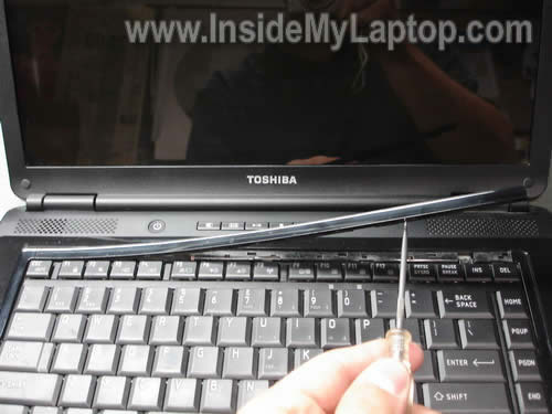
Using a sharp object lift up and remove the keyboard bezel.


Under the bezel you’ll find two screws securing the motherboard. Remove both screws.
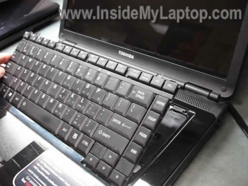
Lift up the keyboard and place it upside down on the palm rest. Be careful, the keyboard is attached to the motherboard.

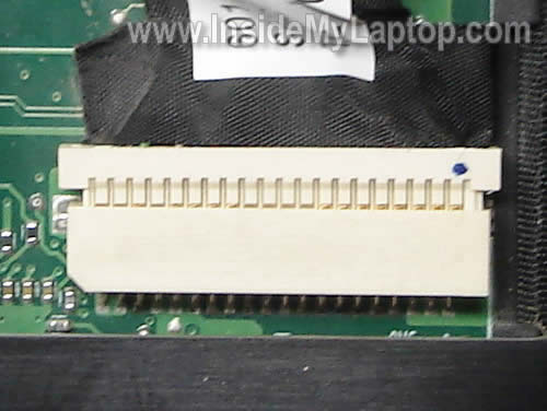
You’ll find the video cable connector under the keyboard.

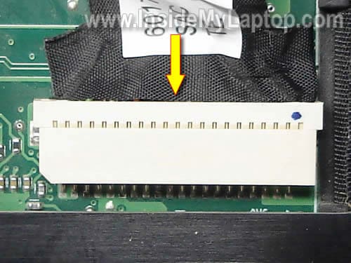
If you look very closely, you’ll see that the video cable is half way out of the connector on the motherboard.

Plug the video cable back into the connector and test the laptop now. Does it help?

How to disassemble Sony Vaio Laptops

4

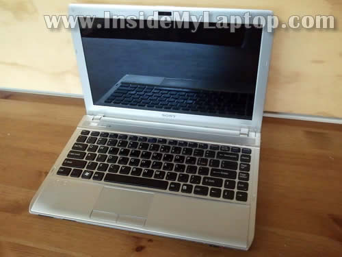
In this guide I will show how to disassemble a Sony Vaio VPCS111FM laptop in order to fix broken power button.
Also, this laptop has another model number on the bottom: Model PCG-51211L.
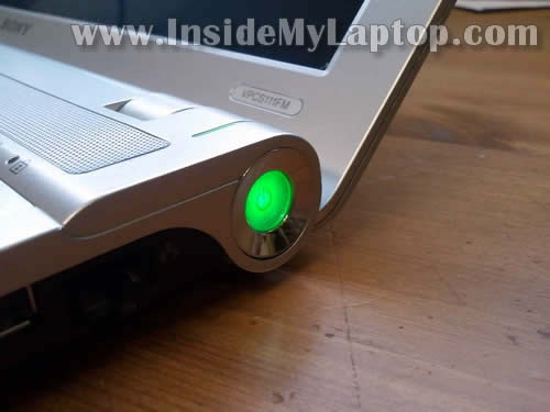
Here’s what happened. The power button got pushed into the laptop case and stopped working. It wasn’t possible to turn on the laptop at all.
In order to figure out what’s going on I had to disassemble the laptop base and take a closer look at the power button.


By the way, here’s my previous post explaining how to replace LCD screen on Sony Vaio VPCS111FM laptop.
STEP 1.
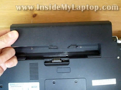
Make sure the laptop is turned off. Remove the battery.

STEP 2.
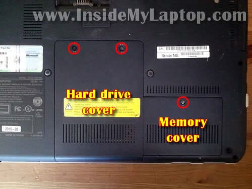
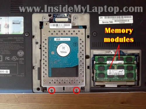
Remove four screws securing the hard drive and memory cover.
It’s not necessary to remove the memory cover for the purpose of this guide. I’m doing it just to show where laptop memory located.

STEP 3.
Remove two screws securing the hard drive assembly.
As you see, both memory modules can be accessed on the bottom of the laptop.

STEP 4.
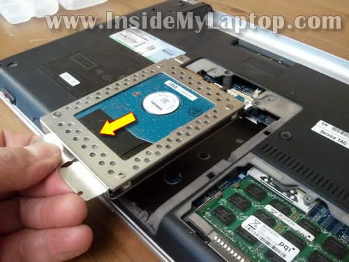
Slide the hard drive assembly to the shown direction to disconnect it from the motherboard.
Remove hard drive assembly from the laptop.

STEP 5.
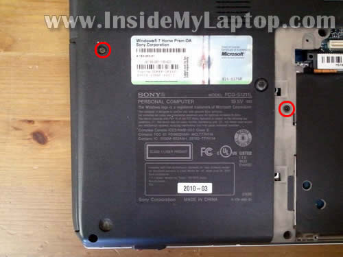
Remove two screws securing the DVD drive.

STEP 6.
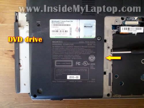
Push DVD drive with a screwdriver and pull it from the laptop.

STEP 7.
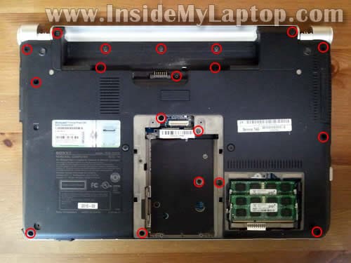
Remove all screws from the bottom of the laptop.
NOTE: my Sony Vaio VPSS111FM laptop had both hinge covers missing. I don’t think you’ll have a problem removing them.

STEP 8.
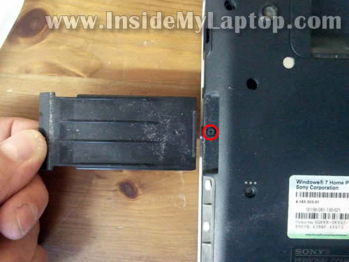
Remove the express card cover.
Don’t forget to remove one screw located under the cover.

STEP 9.
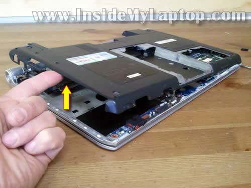
Now you should be able to lift up the bottom cover and remove it from the laptop.

STEP 10.
The bottom cover removed.

STEP 11.
Under the top cover you’ll get access to the cooling fan assembly (fan and heatsink).
If the cooling fan looks dirty, blow the dust off the fan and heatsink.

STEP 12.
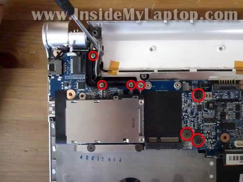
Remove screws securing the express card board.

STEP 13.
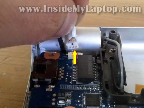
Disconnect the power button board cable from the express card board.

STEP 14.
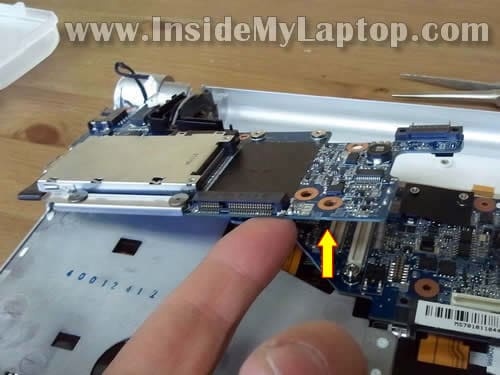
Carefully lift up the right side of the express card board to disconnect it from the motherboard.

STEP 15.
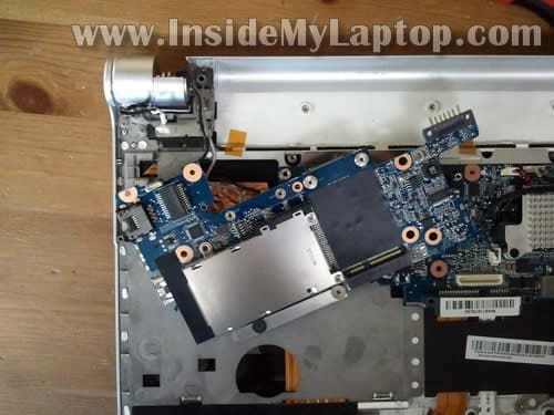
The express card board still connected to the laptop by two wires (wireless card antenna cables). It’s not necessary to disconnect them. Just put the board aside.

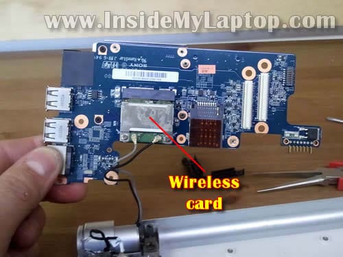
The wireless card attached to the bottom side of the express card board.

STEP 16.
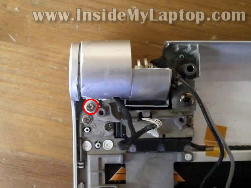
Remove one screw securing the power button cover.
Lift up and remove the cover.

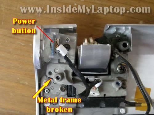
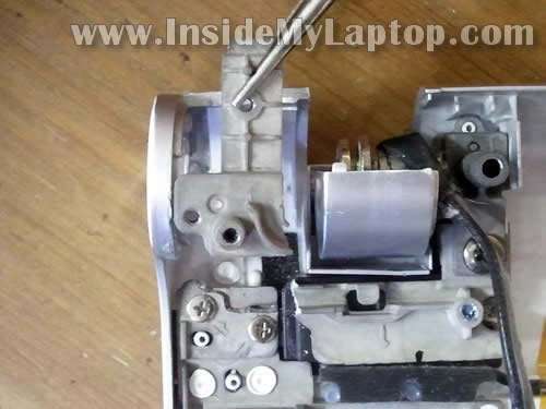
Now you can see why the power button got pushed in.
The power button board mounted on the metal frame which is part of the top cover assembly.
A part of the metal frame where the power button board attached broke off.

STEP 17.
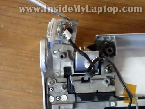
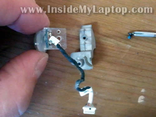
Remove the broken metal frame with the power button.

STEP 18.
Remove one screw securing the power button board to the frame and remove the board.

Now I’m going to glue the broken metal piece back to the main chassis.
I’ll be using JB weld Cold Weld compound to attach two metal parts.

I glued broken parts and let it cure overnight.
The next day I assemble the laptop and voila! The Sony Vaio VPCS111FM power button fixed!

How to disassemble IBM Laptops


In this guide I explain how to replace the cooling fan assembly in an IBM  ThinkPad T43 laptop. This laptop was starting up with a “Fan error” message indicating the cooling fan failure. The fan is a part of the heat sink assembly and when the fan fails, the whole cooling assembly has to be replaced.
Also you can use this guide for removing and replacing the keyboard and hidden memory module.

Turn off the laptop, unplug the AC adapter and remove the battery.
STEP 1.
Remove three screws securing the keyboard on the bottom of the laptop.
The first memory module can be accessed through the door on the bottom.
It’ not necessary to remove the memory module in order to replace the cooling fan.

STEP 2.
Insert a sharp object between the bottom of the keyboard and palm rest and carefully lift up the keyboard.
Place the keyboard upside down on the palm rest.

STEP 3.
Disconnect the keyboard cable from the motherboard.

STEP 4.
Remove the keyboard.
If you are looking for a new keyboard for an IBM ThinkPad T43, you can find it here.

STEP 5.
The cooling fan assembly is hidden under the palm rest and cannot be removed until the palm rest is removed.
The second memory module is located under the keyboard.

STEP 6.
Now we are going to remove the palm rest.
Remove all marked screws from the bottom of the laptop.

STEP 7.
Disconnect the touchpad cable from the motherboard.

STEP 8.
Start separating the palm rest assembly from the laptop base.

STEP 9.
Remove the palm rest assembly.

STEP 10.
Remove three screws securing the cooling fan assembly.
Disconnect the cooling fan cable from the motherboard.
The cooling fan assembly part number is printed on the label.

STEP 11.
Lift up the right side of the cooling fan assembly.

STEP 12.
Remove the cooling fan assembly.

In order to find a new cooling fan assembly, I would suggest searching by the IBM FRU part number. In my case the part number is 26R7950.
You can buy a new cooling fan assembly here.

STEP 13.
Clean up the CPU and GPU chips with an alcohol swab.
Do not forget to apply fresh thermal grease on the CPU. You don’t have to apply thermal grease on the GPU because it will be covered with thermal pad located on the heat sink.

A new cooling fan assembly should come with thermal grease pre-applied on the heat sink. Also, it comes with thermal pad for the GPU.
How to disassemble Lenovo Laptops

 
In this post I explain how to replace a noisy or failed cooling fan in a Lenovo ThinkPad T61 laptop.
This guide might work for some other Lenovo ThinkPad models. If it works for you, please mention the laptop model number in the comments after the post.
The cooling fan is a part of the heat sink assembly. If the cooling fan fails, the whole heat sink assembly has to be replaced.
It’s possible that you can separate the fan from the heat sink and replace it separately, but in this guide I’m replacing the whole assembly.
Let’s remove the cooling fan assembly and replace it with a new one.

Turn off the laptop, unplug the AC adapter and remove the battery.
STEP 1.
Remove four (red) screws securing the palm rest.
Remove one screw (yellow) securing the keyboard.

STEP 2.
Lift up the palm rest.

STEP 3.
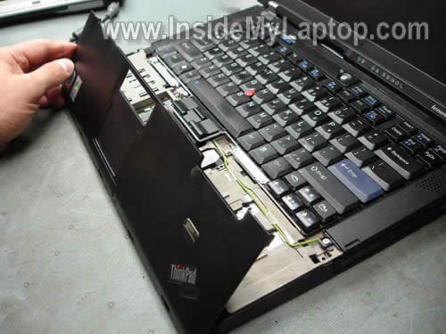
Place the palm rest upside down so you can access the touch pad cable underneath.
STEP 4.
Disconnect the touch pad cable from the motherboard.
By the way, both memory modules are located under the palm rest. If you are replacing or upgrading memory modules, you don’t have to follow the guide any further.
A Lenovo ThinkPad T61 laptop can take up to 4GB RAM total. You can install up to 2GB memory module into each slot. You should use DDR2 PC2-5300 or PC2-6400 memory modules.

STEP 5.
Lift up the keyboard and place it upside down.

STEP 6.
Disconnect the keyboard cable from the motherboard.
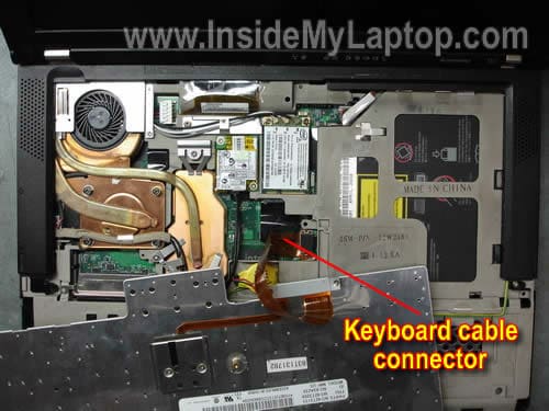
In order to disconnect the cable simply lift up the the connector, same way you disconnected the touch pad cable.
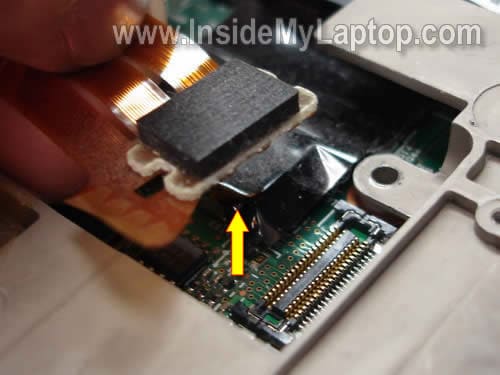
If you are replacing the keyboard, you don’t have to follow this guide any further.
You can find a new replacement keyboard by the Lenovo FRU part number printed on the label. In my case the keyboard part number is 42T3209.
Need a new keyboard for your Lenovo ThinkPad?  Search here.

STEP 7.
Remove three screws securing the speaker cover.
By the way, the CMOS battery is located under the keyboard.

STEP 8.
Remove two screws securing the speaker cover on the bottom of the laptop.

STEP 9.
Remove the speaker cover.

STEP 10.
Remove four screws securing the cooling fan assembly brackets. Remove both brackets.
I would recommend taking a close up picture of the lower bracket, so you know how the wires are routed. The picture will help you to rout wires correctly when you assemble the laptop back together.

STEP 11.
Remove two screws securing the left speaker.
Disconnect connectors shown by two arrows.
Move the left speaker with cables to the right side, so you can get to the cooling fan assembly.

STEP 12.
Disconnect the cooling fan cable from the motherboard.
Remove four screws securing the cooling fan assembly.

STEP 13.
Lift up the cooling fan assembly as it shown on the picture below.

STEP 14.
Remove the cooling fan assembly from the laptop.
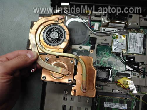
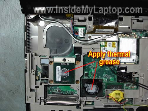
If you are replacing the failed cooling fan assembly with a new one, most likely the heat sink already has thermal grease pre-applied.
On the other hand, if you are installing a refubished cooling fan assembly, you’ll have to apply thermal grease on both chips shown below.
You can search for a replacement cooling fan assembly by the Lenovo FRU number from the failed fan.
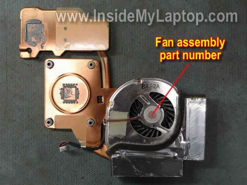
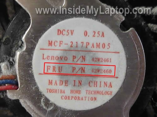
The FRU number is printed on the label. In my case, the FRU part number is 42W2460.
You can find a new or used cooling fan assembly here.